
Installation packages are available for download at the Keysight Technologies Calibration website.
This topic includes the following sections:
Refer to the Readme.txt file for information on the compatibility of this package with previous versions of the application and the Test Management Environment (TME) test executive.
Refer to the Readme.txt for information on the minimum system requirements to run this application.
|
|
Installation packages are available for download at the Keysight Technologies Calibration website. |
There are two ways to install TME and its applications:
Network Installations — Equipment and test data information is stored in a central location (the TME Server). This data is shared among a set of TME Clients. Multiple test stations can then have access to this central information.
Local Installations — Everything is installed on one PC
In a network installation, order information is stored centrally and can be accessed by any TME client in the network. This allows you to combine data from tests that were run on multiple stations into a single report. Equipment data and order information are also accessible from any station.
|
|
|
To install an application on a network, follow these steps:
Find the PC where the TME network was installed (Shows “TME Server” in Add or Remove Programs).
Run Setup.exe for the application on that PC. This will install all networked components for that application.
Install application clients:
TME clients will be asked to install the application the next time TME is started.
or
Applications can be installed by running the setup file from the network directory:
\\FileServer\Test Management Environment\Install\(AppName)\(AppName)ClientSetup.exe
|
|
The client setup must be run from this location. It should not be moved or renamed. |
On a local installation, all application data is stored on the target PC. TME must be installed on the target PC before the application installation can occur. Once TME has been installed as a local installation, the application will automatically install locally when executed. Order information, test results, and equipment data will not be shared with other users.
To remove pre-E.01.00 versions of TME and its applications before installing a newer version, please refer to Installing Over Previous Versions.
|
|
If you uninstall TME completely or uninstall any TME application, you will lose the data associated with those applications. Create any reports needed and save them as PDF files before you perform any uninstallation of that product. |
To uninstall a previous version of TME, please see Installing over Previous Versions.
To uninstall TME or any TME application, select that package from Add or Remove Programs.
To uninstall an application client, select that package from Add or Remove Programs on the Control Panel.
|
|
Data will not be lost if only a client is uninstalled. Other clients will still have access to the data in the network. |
To uninstall an application server:
Follow the directions above to uninstall all application clients first.
On the PC where the server installation was performed, select the application server from Add or Remove Programs on the Control Panel and click Remove.
To uninstall an application local installation, select that package from Add or Remove Programs on the Control Panel and click Remove.
Before adjustments can be run, a prerequisite procedure must be performed. This is necessary so that the N7828A application can communicate with the VXG over the LAN. The procedure involves copying a set of files from the host PC (the PC where TME is installed) to the VXG and running a service program during adjustments.
Complete instructions can be found in the Prerequisite Procedure for Adjustments topic.
This section describes the preparation of the instruments used by the test software at a given test station. The test software does not check instruments for proper operation on the GPIB or LAN before attempting to perform tests.
The following table lists a test station's typical GPIB address configuration:
|
Signal Generator |
19 |
|
Power Meter |
13 |
|
Frequency Counter |
03 |
|
Spectrum Analyzer |
18 |
|
Network Analyzer |
16 |
|
DVM |
22 |
|
Function Generator |
10 |
|
Oscilloscope |
4 |
Use the following steps to manually check for proper connection of the GPIB devices before performing tests on a newly connected test station.
|
|
The GPIB address of each instrument associated with the test station/test plan is defined when you configure a test plan. |
Connect a power cord to each instrument, then connect each instrument to the computer serving as the GPIB controller.
Power up all the instruments on the GPIB bus.
Check each GPIB instrument for proper communication
over the bus and the required detectable options,
as described in the following section.
|
|
When checking the basic operation of each instrument or when checking for detectable options on a given instrument, you may need to look up the actual command for retrieving the identification string before performing these steps. |
Start the Keysight Connection Expert from the task bar or access it through Start > All Programs > Keysight Connection Expert.
Check for all expected GPIB devices. Verify that all expected GPIB devices are shown in the left window. If a device is missing, correct the problem and re-scan for connected instruments.
Check for basic operation of each GPIB device:
|
|
If an instrument does not support SCPI, refer to the user guide for the product to learn more about checking the basic operation of its GPIB. |
Select a GPIB device.
Select the Interactive I/O from the right window.
The command window should be pre-populated with the *IDN? query. You can also select from the Commands > drop-down menu, or simply type *IDN? in the command window.
Select Send & Read.
Verify that the expected model number is contained in the response text string.
Check for detectable options on a given device:
|
|
This does not work with the power meter. |
Select a GPIB device to highlight it.
Select the Interactive I/O from the right window.
Type *OPT?
in the command window.
Select Send & Read.
Use the following steps to manually check for proper connection of LAN devices before performing tests on a newly configured test station.
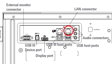
Verify that the device is connected to the LAN using the proper connector.
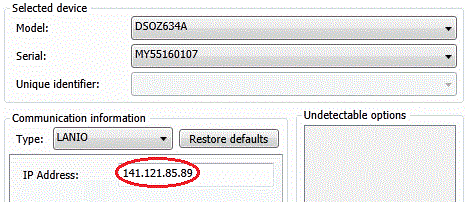
Determine the LAN address of the device. For the Infiniium Z-Series Oscilloscopes, this can be found under Utilities > Remote… > Web Address.
Ensure that the proper IP address has been configured for the device in TME.
Verify that the device can be detected in Keysight Connection Expert.
Start Keysight Connection Expert from the task bar or access it through Start > All Programs > Keysight Connection Expert.
If necessary, add a LAN interface using the Add Interface button at the top.
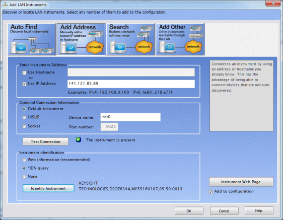
With the LAN interface selected, select Add Instrument.
Select Add Address.
Select Use IP Address and enter the IP address on the instrument.
Click Test Connection and verify that the instrument is detected.
Under Instrument Identification, select *IDN Query.
Click Identify Instrument and verify that the model and serial number are correctly reported.
Protection against ESD (electrostatic discharge) is essential while connecting, inspecting, or cleaning connectors attached to a static-sensitive circuit (such as those found in test sets). Static electricity can build up in your body and can easily damage sensitive internal circuit elements when discharged. Static discharges too small to be felt can cause permanent damage. Devices such as calibration components and devices under test (DUTs) can also carry an electrostatic charge. To prevent damage to the test set, components and devices:
Always wear a grounded wrist strap having a 1 million Ohm resistor in series with it when handling components and devices or when making connections to the test set.
Always use a grounded antistatic mat in front of your test equipment.
Always wear a heel strap when working in an area with a conductive floor. If you are uncertain about the conductivity of your floor, wear a heel strap.

